To install the pinion gear, warm up the casing and press in the pinion gear using the old pinion gear as a guide. If you don't have a press, you can carefully tap it in. It doesn't take much force to get the bearing in.


The new pinion gear seems to be a bit longer than the old one. Had to grind off the end of the shaft.

Insert the needles of the needle bearing using sticky grease. Be sure the bearing hole is clean.


The 3304 bearing need to get pressed on to the pinion gear shaft. I don't have a press, so I used the machine vise. Used a 0.3mm shim between the bearing and the gear.

Everything is ready to assemble. The bearing nut (large yellow colored nut on the right) needs to hold the pinion gear without any play. Use those star shaped washers in case.


Be careful to secure the hub to not damage the main seal and to not block the drain hole by misaligning the seal.
Check if the main rubber seal has the correct seat at the bearing surface of the hub and the spring is in place. This is one of the main reasons for leaking FDs.

The final drive is assembled and can be installed.


New final drive in service.
Very quiet and does not get hot after a longer ride 😺

The reason for a side-to-side play in the rear wheel is because of the play between the wheel bearing and the axle. The bearing inner diameter is 20mm, and the outer axle diameter is about 19.95mm.
For the new final drive, I will make a new axle out of 4140 steel to have a transition fit. The bearing should slide without play on the axle.


To center the hole for the split, the drill is positioned to have the ruler horizontal.

Top one is the new axle.

To make the access to the nut easier, I made the axle a bit longer and made a large distance washer.


Make the distance washer the same color as the nut.


Test fit. No wheel play and the axle easily slides in and out.
Passed.


Easy access to the nut.

To support the wider brake pads used along with the M5 wheels on the CJ750, the existing brake cam and holder gets replaced.
Using plastic placeholders to get the correct size for a good fit.


The brake cams are made out of 4140 steel.

Transitional fit for no-play brake cams.


The new brake cam set.
The leading edge of the cam is rounded with a file.

The final drive is inserted and rotated a few times. This aligns both brake pads with the self-adhesive sandpaper to maximize braking power. The sandpaper is then removed and the inside is cleaned with brake cleaner.

The distance from the ring gear to the pinion gear is set by shims between the cover and the bearing. Often the hub with the bearing is pressed on to the cover, making adjustments with different shims difficult.
For this reason, the tubular holder in the cover is made for a perfect fit without the need for a press. Very careful sanding with a fine grid paper will get a transition fit.
The pinion gear will always push out the ring gear towards the cover. Along with the o-ring in the drive shaft, additional push is provided to keep everything in place.
The gear compound at the top of the shaft is to check for any contact with the hub. Often a common source for noise.

The 1-3/8"x1-7/8" Arbor Shims are used to space the ring gear. The M52x42x0.2 shims are used to space the pinion gear. The M52 shims were sold in a pack of 125 only.


To make the pinion adjustment easier, a plastic replacement for the bearing with a undersize is used to allow quickly sliding the pinion gear in and out.

Gear compound is used to see the contact pattern.

The contact pattern gets visible once the gear is rotated. Apply some pressure to the ring gear when rotating the pinion gear to get a clear pattern.

Rotate forth and back to get a pattern for the cruise and drive side.
This is the drive side. Needs adjustment.

This is the cruise side. Also not acceptable. The distinctive bottom line must not appear. The pattern should be uniform and gradually fade out.

Guide to adjust the contact pattern.
Search for contact pattern to get more detailled guides on how to adjust the gears.
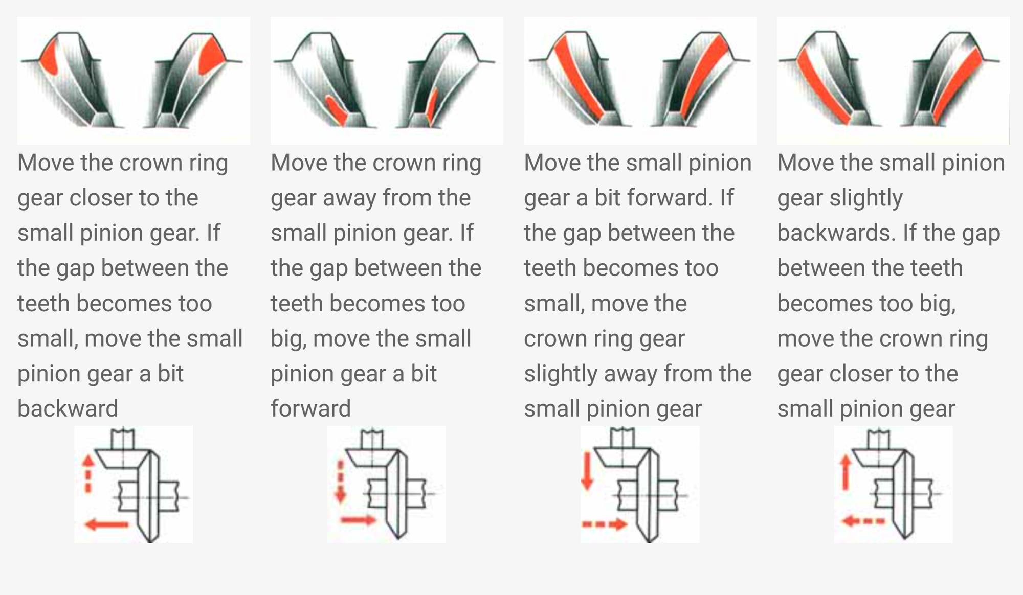
Using the contact pattern guides, move the ring gear by adding or removing 1-3/8"x1-7/8" Arbor shims between the cover and the hub bearing, and move the pinion gear by adding or removing M52x42x0.2 shims between the housing and the bearing.
Acceptable contact pattern for the drive side.


The distance bushing is made out of 1"x0.12"x0.76" DOM Mild Steel Tube A513 and drilled to an internal diameter of 20mm on the lathe. The old one was rather sloppy and was not perfectly even.

Check the distance and the seating of the driving gear. I have put a large o-ring inside the wheel hub to push the hub towards the cover. This ensures the ring gear always seats against the cover and maintains proper distance of the gears.
The CJ750 FD does not use the bronze slitted washer to keep a minimal distance between the ring and pinion gear, and with the o-ring on the wheel side, the ring gear never slides towards the pinion.


The M8x14 1.25 bolts, class 10.9, to connect the hub with the ring gear are secured with red loctite 272.


The bolts are torqued to 32Nm.


Clean the casing and cover surfaces and place the seal. Check the orientation as there is only one valid hole pattern. I used the one with EU quality from ural-zentrale.


The suspension spring on the old final drive (FD) needs to be removed as it is reused for the new FD. It turned out that the measurement of the new suspension spring is different from the old one. It is only a small amount, but left and right suspension side need to match.
Level 1 of spring removal
The cap of the spring has a small hole to access the end of the spring and can be tapped out with a punch through the small hole. Simply twisting the spring will not work as the spring tightens when turned. Tapping will move the spring the opposite direction to unscrew from the holder.
Not the case here.
Level 2 of spring removal
Small access hole in the cap is not in the correct position and cap needs to be turned to access the end of the spring.
Not the case here.
Level 3 of spring removal
Everything is stuck. The cap won't turn, and the end of the spring is in a position that is not accessible to tap out.
This is the case here.
The surgery starts with the removal of the cap. The endmill is positioned to not cut all the way through the metal to not damage the spring.


Carefully bending back and forth.


To try to turn the spring, a spanner is modified to hook into the end of the spring.

The position of the end of the spring is tight. The spanner need to be rather thin on the end to reach the spring position. Usually it doesn't take too much force to get the spring started, but unfortunately the spring is too tight and the spanner fails and the end of the modified spanner breaks.
Upgrade to level 4 of spring removal.

Level 4 of spring removal
The cut.
I have only this perfectly matching spring, but enough of FD covers. The cover needs to go.

The spring tension cause the blade to break and get stuck halfway through the cut.

The spring is separated, but the guide for the suspension rod is still stuck.

The plan is to make a saw cut from the inside.

The guide consists of two parts. The inner part can now be tapped out.


The outer part of the guide needs to be very carefully cut to not damage the spring.

Left side is the newly ordered spring, right side is the rescued spring.
