| CJ750 toolbox | |||||
| Rebuilding a CJ750 M1M by Bart Sanders | |||||
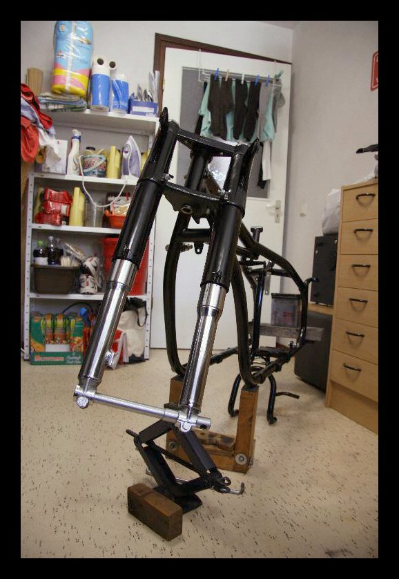 |
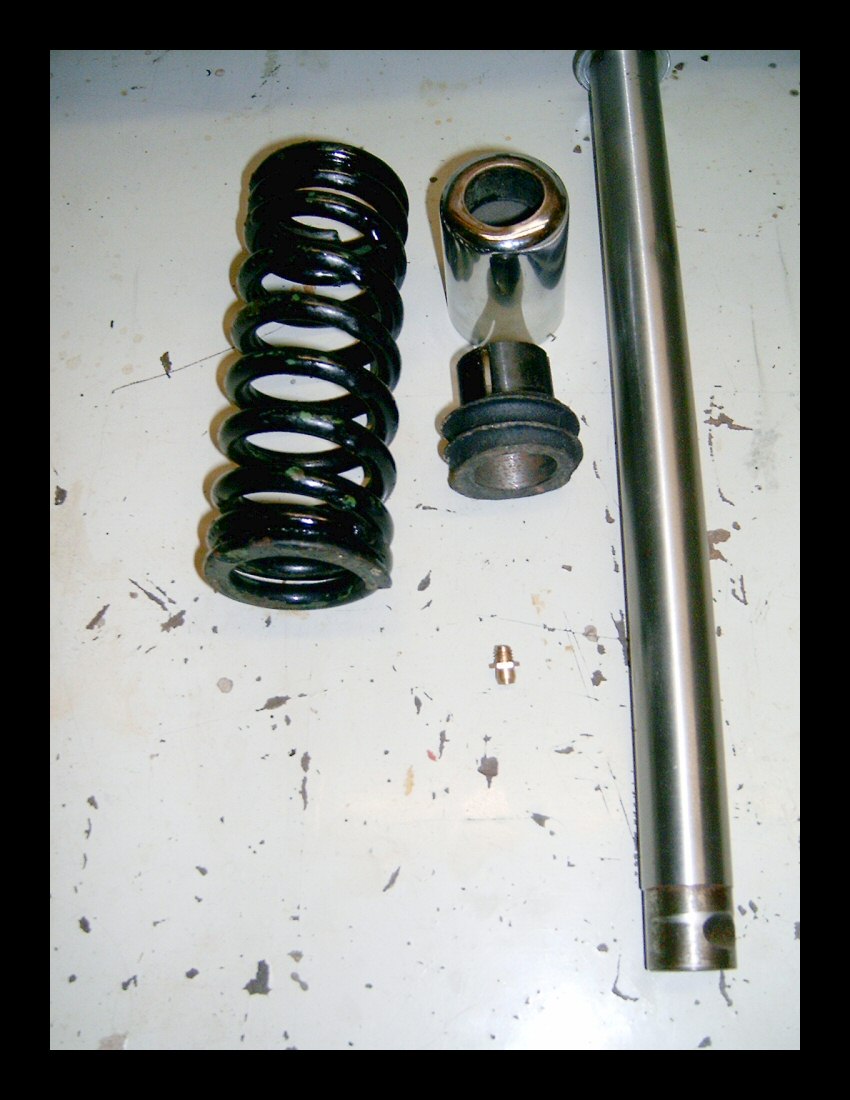
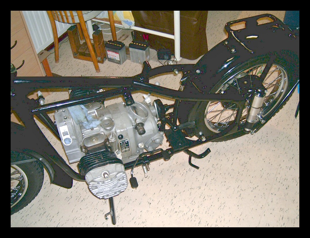
Here are the first images of my re-building project of a CJ750 M1M. Before taking it apart, I have checked the engine-transmission-drive for some 280kms. All that seems to work fine. But the frame, front fork and electric cabling needed attention, so I stripped it completely. | ||||
| The front fork lower right bearing bushing had way too much play in its tube, so I replaced it with a new one and honed the lower tube until the bush goes up and down smoothly, but without play. A tedious, but rewarding job leading to a fork without any play. | |||||
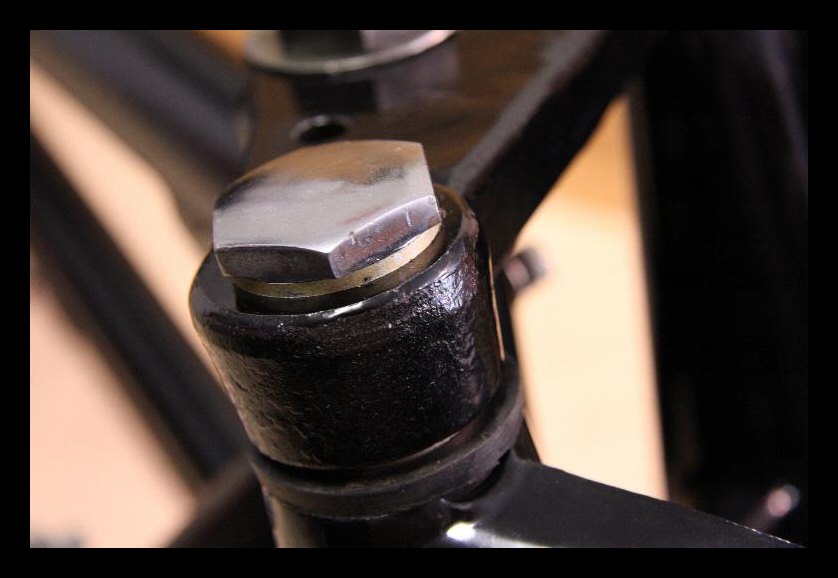 |
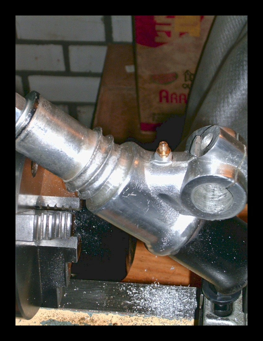
A second point of attention proved to be the upper crown-plate. The mounting surfaces for the two large chrome bolts where skewed and not machined to flat and perpendicular faces with respect to the fork tubes center-lines. | ||||
| Thus, the two big bolts only rested on one elevated point instead of resting/using the whole circular surface. Putting the crownplate on a mill and flatten the two surfaces cured that problem. This is one of the points on which the structural strength of the biks depends upon, so it better be good. | |||||
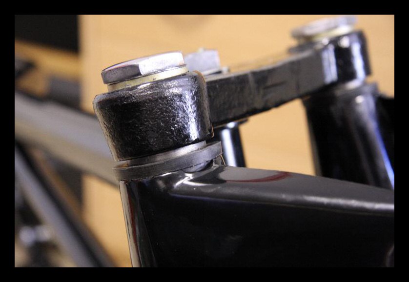 |
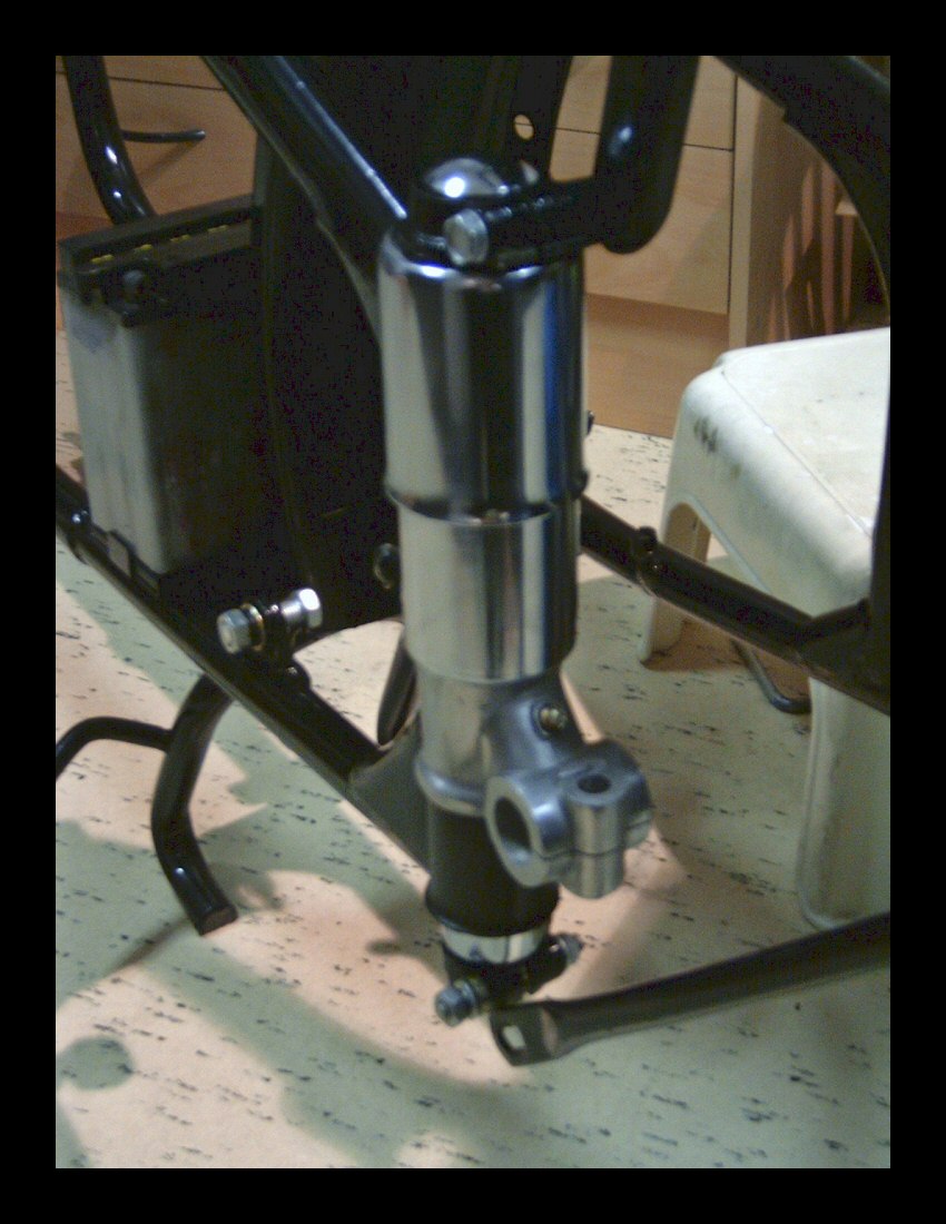
Finally, the two lamp-holding sleeves with their upper centering rubbers showed some millimeters of space between the upper crownplate and the rubbers. I severely suspect the crownplate to be out of specs. Anyway, a couple of filler rubber rings compensate for this easily! | ||||
| Part II - Replacing the battery plate from right-aft to just behind the kickstarter | |||||
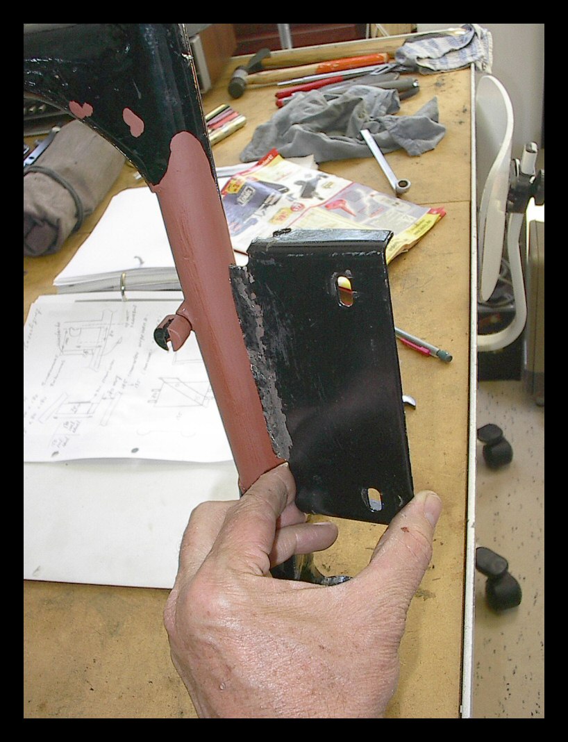 |
First cut off the old plate to the right of the frame. Then use your tools to get rid of the welds and make the tube smooth again. Paint and off you go. | ||||
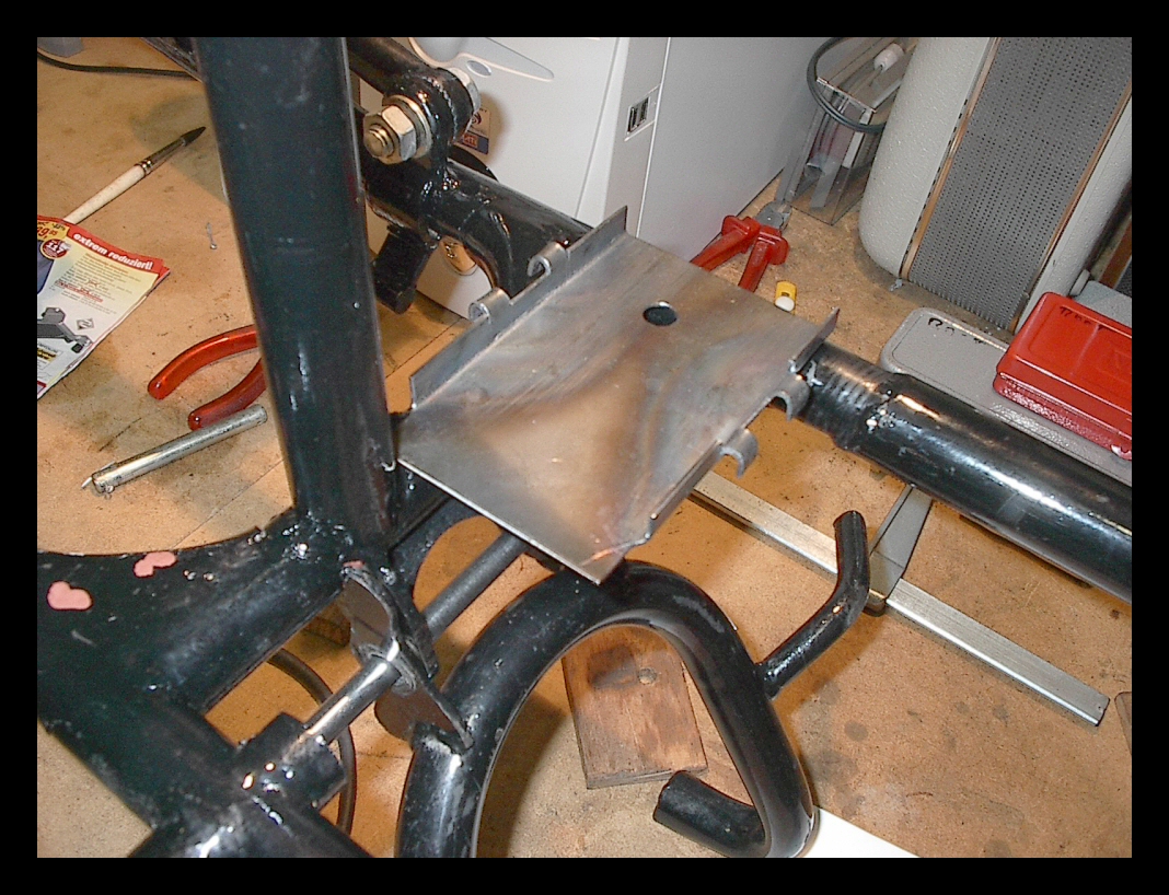 |
Take a piece of 2mm sheetmetal and use your jigsaw and wrench to make a new battery-holding-plate. | ||||
 |
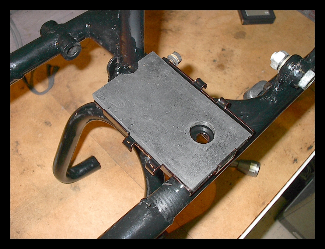
I decided to use M4 and M5 screws to fix the plate in its position. It's a good solution for future removal, should this be necessary. | ||||
 |
Re-use the rubber cushion under the original battery and make a new, smaller one out of it. Note the water drain hole. | ||||
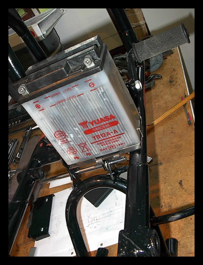 |
Et voilà! Your new battery location for modern, small but powerful batteries. This one is from our Honda CB350F and the startmotor from the M1M just runs fine from it. | ||||
| Part III - Mounting the rear mud guard | |||||
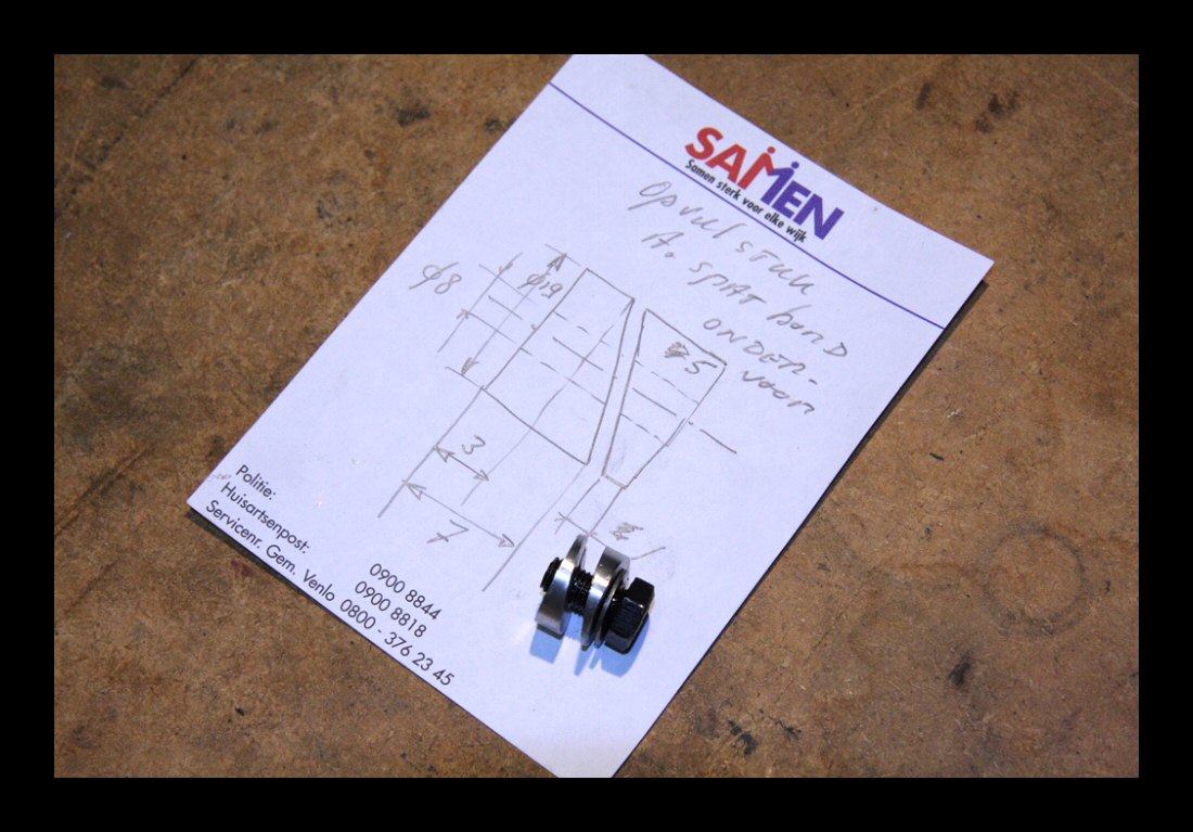 |
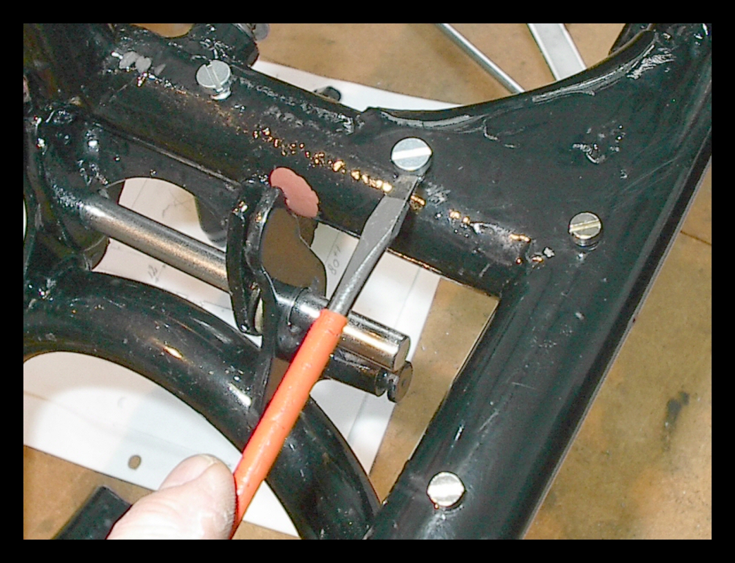
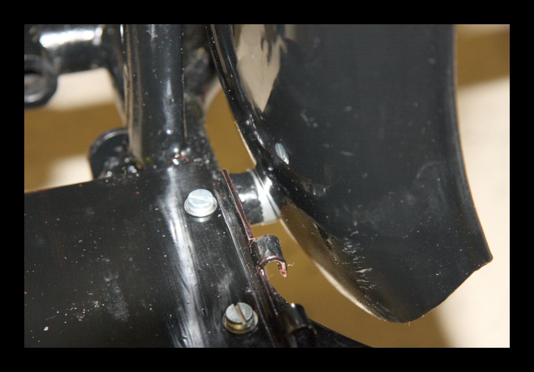
Changs are not expensive, but do we therefore need to cut corners during assembly? No! The rear mud guard is also fixed to the frame at the bottom end of the central reinforcement tube below the saddle. Fine. What is not fine is the fact that the mounting surface does not follow the curvature of the mudguard at this point. One can now simply tighten the bolt not minding the strong deformation of the sheet metal thereby cracking the paint surface. | ||||
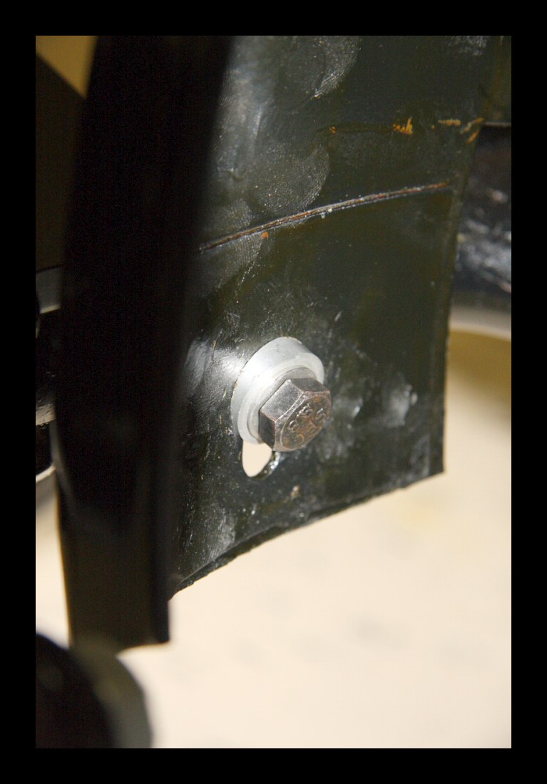
| One can also make two filler rings which compensate for said curvature. That's what I did. It fits perfectly, no tension in the mudguard and the paint stays intact. | |||||
 |
That's not cutting corners! The rear suspension sometimes lacks a grease nipple! | ||||
 |
Once in awhile I see no grease nipple in the left rear suspension body. However, it's always present in the rear drive body. Whatever the cause, it must be there. | ||||
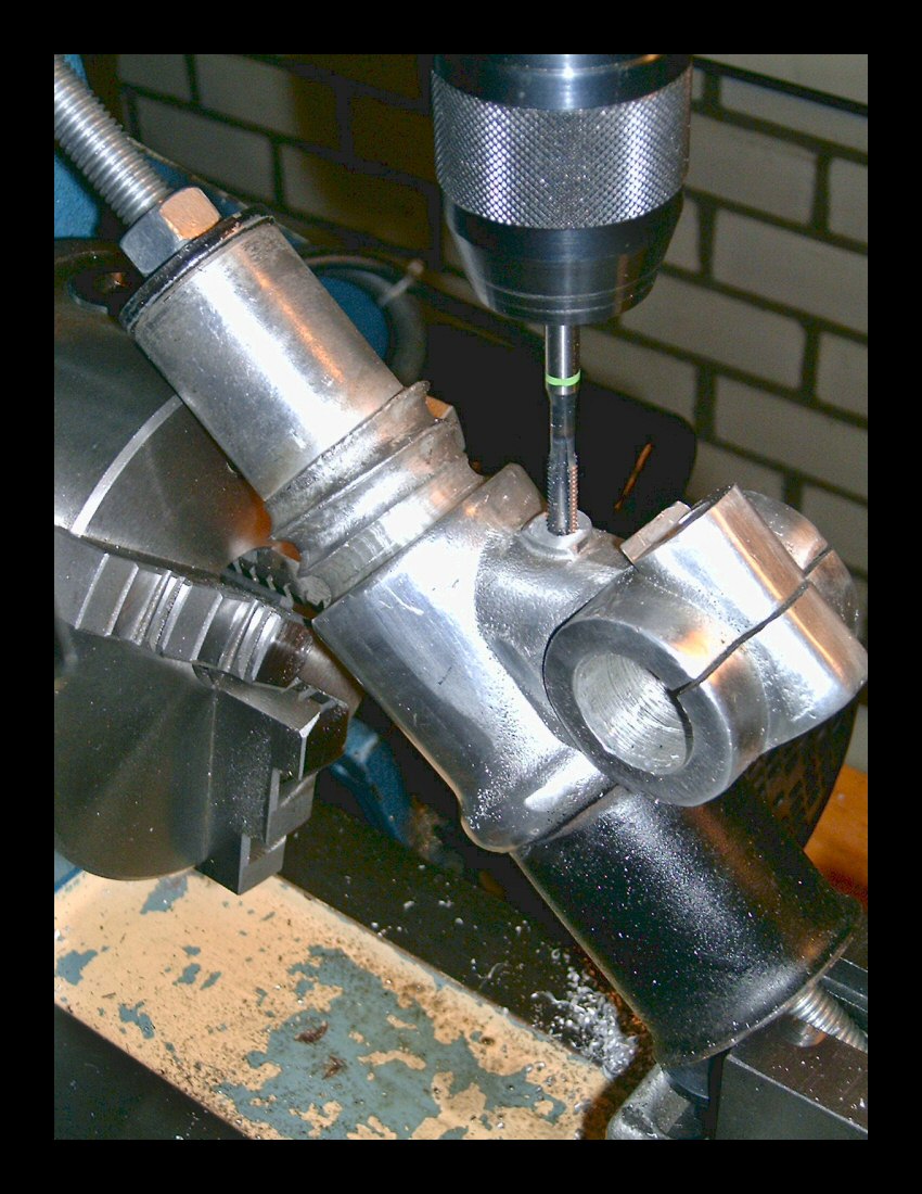 |
The left suspension body installed in a mill and the missing grease nipple thread is about to become ready. | ||||
 |
The tiny grease nipple looking for a new home.... | ||||
 |
Found! This is how the engineers designed it and it certainly needs a grease job every 1000 km. The slider bearings are perfect and show now play with the central shaft, but if not lubricated well, things start to corrode and somewhere down the road the suspension gets stuck. So, if your Chang also misses this nipple, get the suspension out and let somebody do this job - or do it yourself. | ||||
 |
All in place now and working like a charm. | ||||
| Part IV | |||||
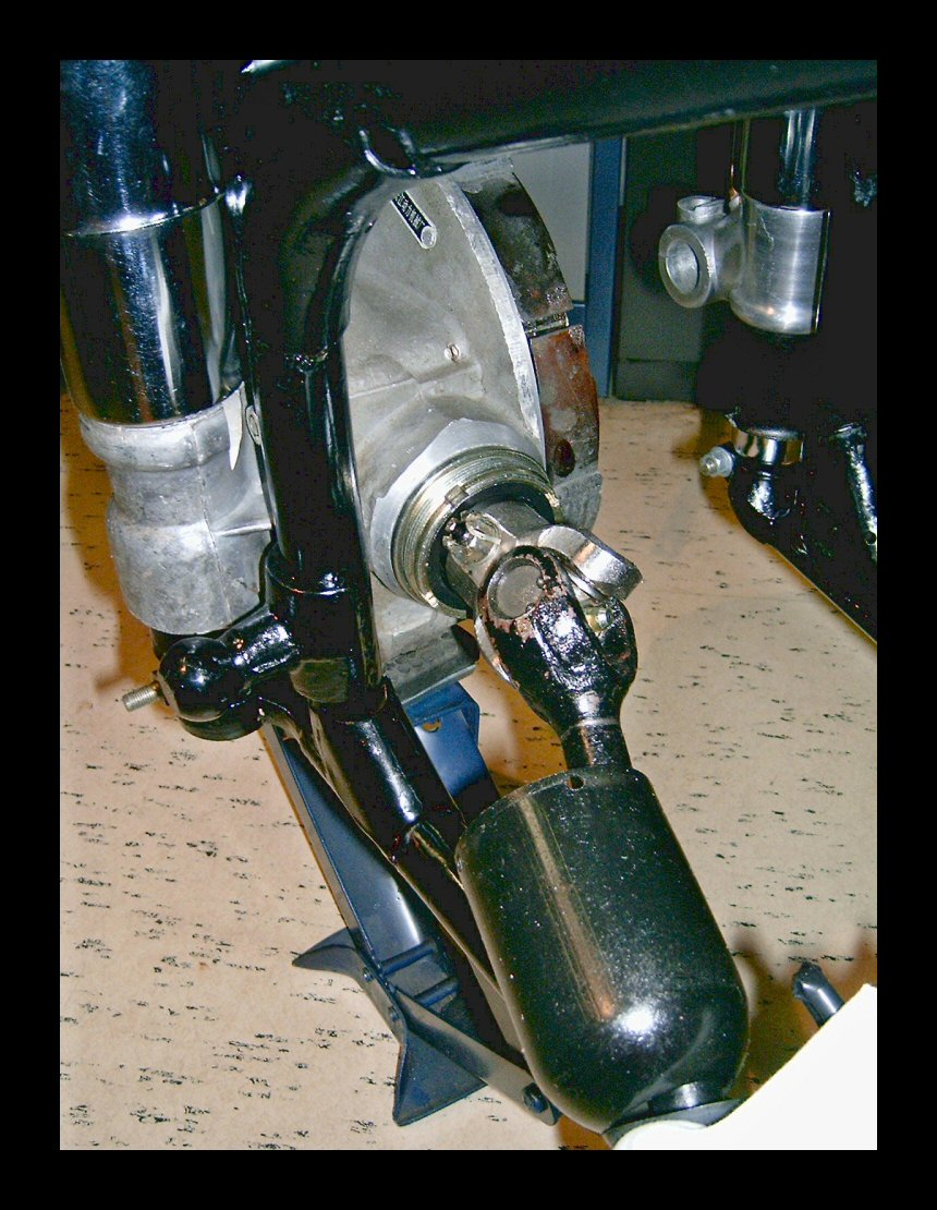 |
The spring and drive construction on the right side of the bike have just been installed. This is a very good moment to pick up your grease-gun and grease the cardan-cross via its nipple. Please note that this bearing must be greased every 1000km! It's an un-easy location once everything is installed, but it can be done. | ||||
| Pull away the rubber sealing, remove the bell shaped dome (loose is clockwise, left thread!) and turn the rear wheel so that the grease-gun can be applied correctly. | |||||
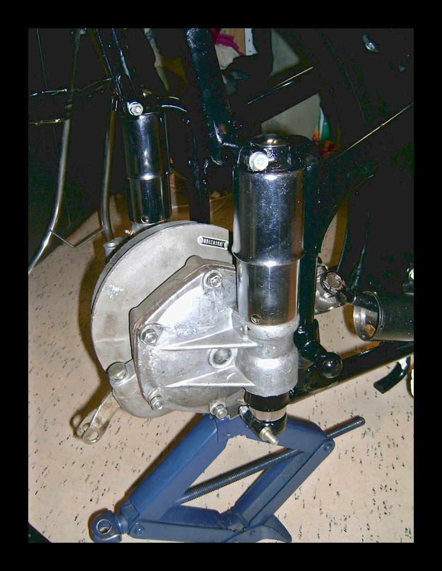 |
Before you tighten the upper and lower pinch-bolts, jack-up the drive against the spring and compress the spring a bit, use your plastic hammer and hit the chrome cap a few times mildly so that everything here sits well. Then tighten the upper and then the lower pinch bolts. The drive now hangs correctly and should stay in its place. | ||||
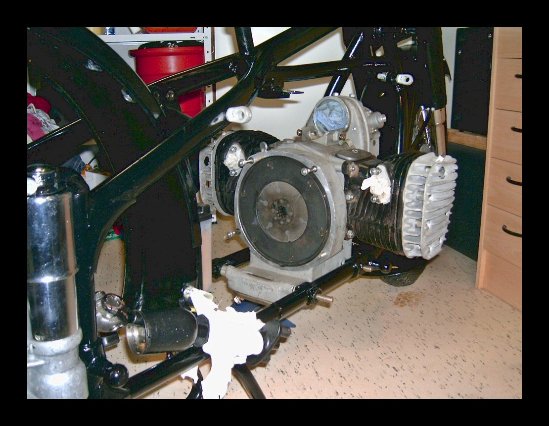 |
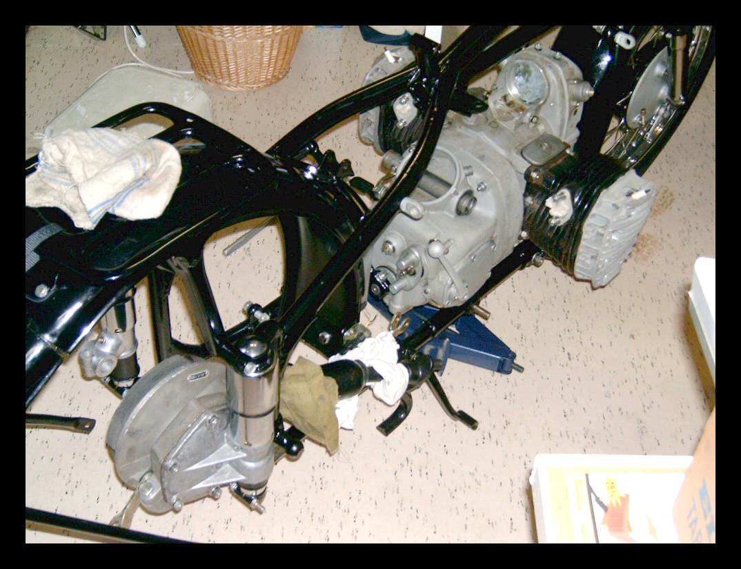
Position your jack between the frame tubes around the expected center of gravity of the engine. Set it at the correct height. Install the engine from the right side, tilt the left cylinder up, slide the bottom end between the frame tubes and put the engine on your jack. Then slide the engine back or forth to position it against the frame mounting holes. | ||||
| Thin filler rings at the right side, thick filler rings at the left side of the engine. Slide in the long bolts, first the backside (longest bolt), then the frontside (shortest one). Using two pair of hands makes the job easy. | |||||
| Part V - Mounting the gearbox | |||||
 |
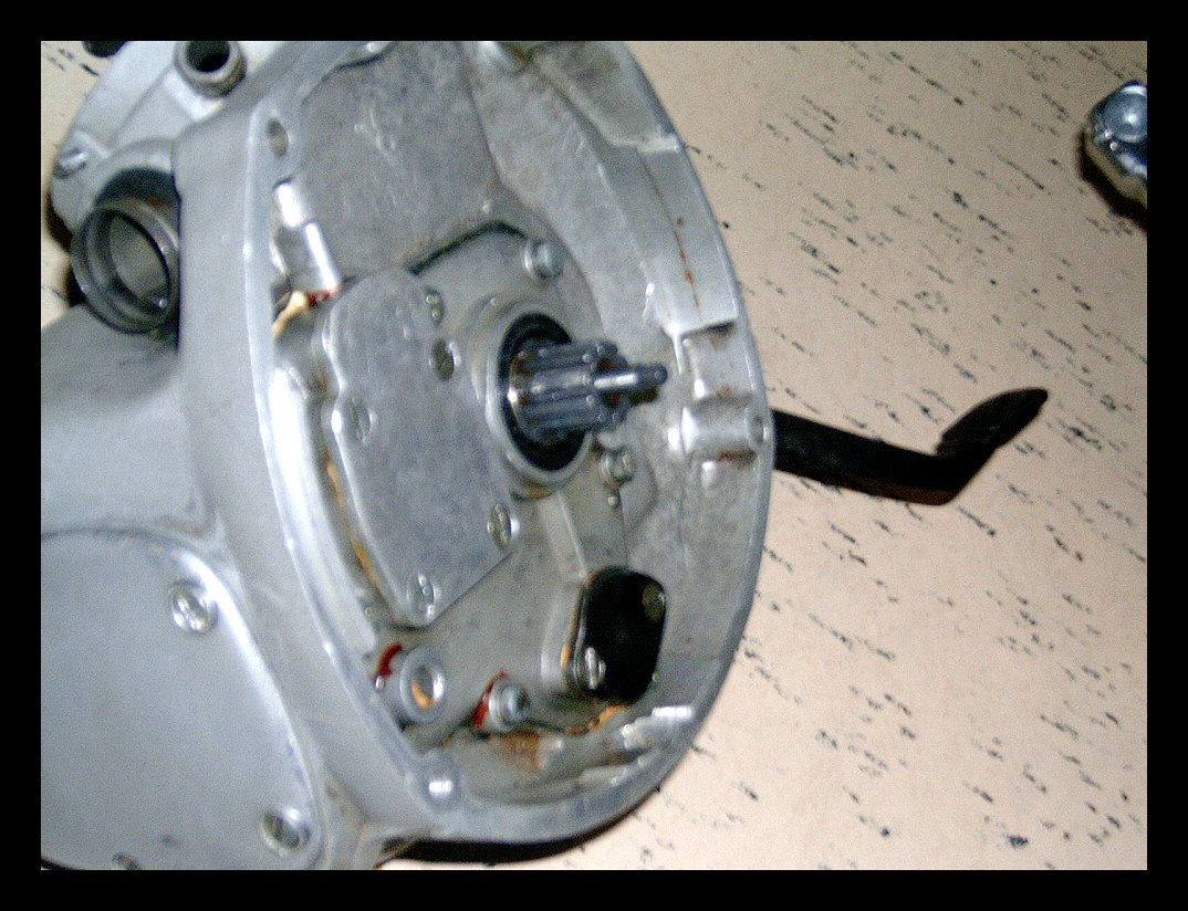
Ever want to clean up the joint between axle and hand-shift lever? Well, I did. So, I took the key-bolt out, removed the lever and saw the axle march some 5mm into the gearbox. Oops? Now the key-bolt could not align anymore with its key and could not move in anymore. First of all I cleaned the surfaces and left it to rest. Sometime later, a stroke of genius! | ||||
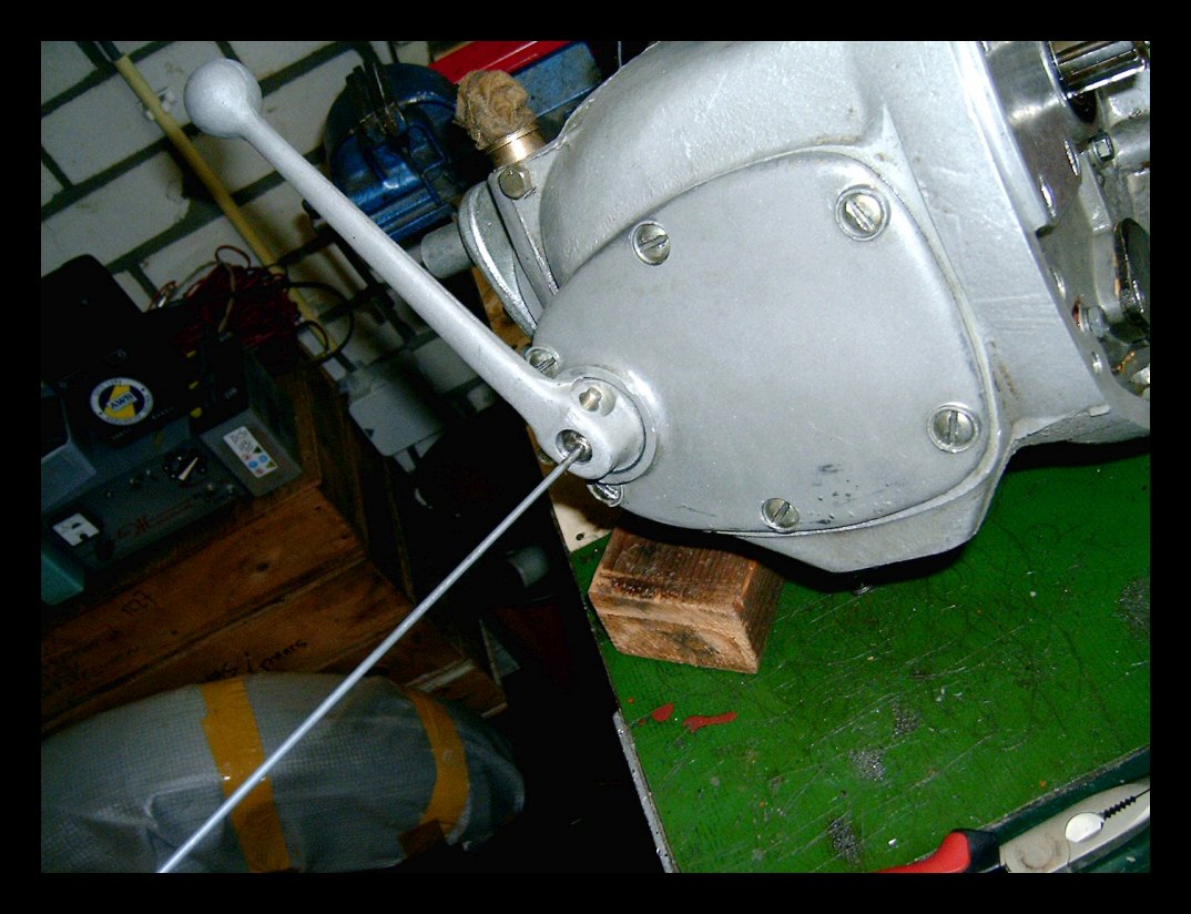 |
If I could only fix a piece of wire to the axle's center, then I could pull the axle back against its inner spring and shift the key-bolt in. I used soft soldering for fixing the wire. Using a mild flame just at the axle's end, the solder would flow and make a good joint. The rest was a piece of cake. Pull back the axle, align the lever and the key slot and the joint was fixed again. Washer, ring and nut. All was OK. Not rocket-science, but a neat trick to my belief! | ||||
 |
Another nice alignment task is the job of getting the clutch pushrod exactly before the square hole and shift the tranny in its final position. Do not try to do it like this: mount the tranny, shift the pushrod in from the back and hope that it will find its hole. It won't. Better approach: put all the clutch parts in, pushrod, axial bearing assembly and finally the push mushroom with its O-ring. | ||||
 |
Use Molykote for good early lubrication when no oil is present yet. Then grease the splines of the central axle and the clutch-plates with not too much Molykote. This is an important step. Your clutch will work much better this way. Now push the axial bearing assembly inwards until it stops, then pull out the pushrod some two centimers more. Position the tranny so that you still have some working space for a pair of pliers. | ||||
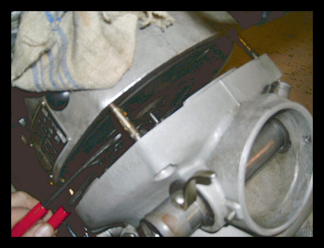 |
Use the pliers to shift the pushrod in even further. If you noted the position of the square hole (say the edges are vertical/horizontal) and kept the pushrod accordingly, it will almost slide in by itself. Now slide the tranny over the three threaded studs until it snaps into its final position. The axial bearing will be pushed back again to its final position. Ready! | ||||
| (Oh yes, nice tip aside: If your tranny does not want to slide onto the three studs, then take out the back engine mount bolt, lift the engine just a bit using a jack below the oil drain area and the tranny will move in with great ease. Lower the engine, put the bolt back in. Continue.) | |||||
 |
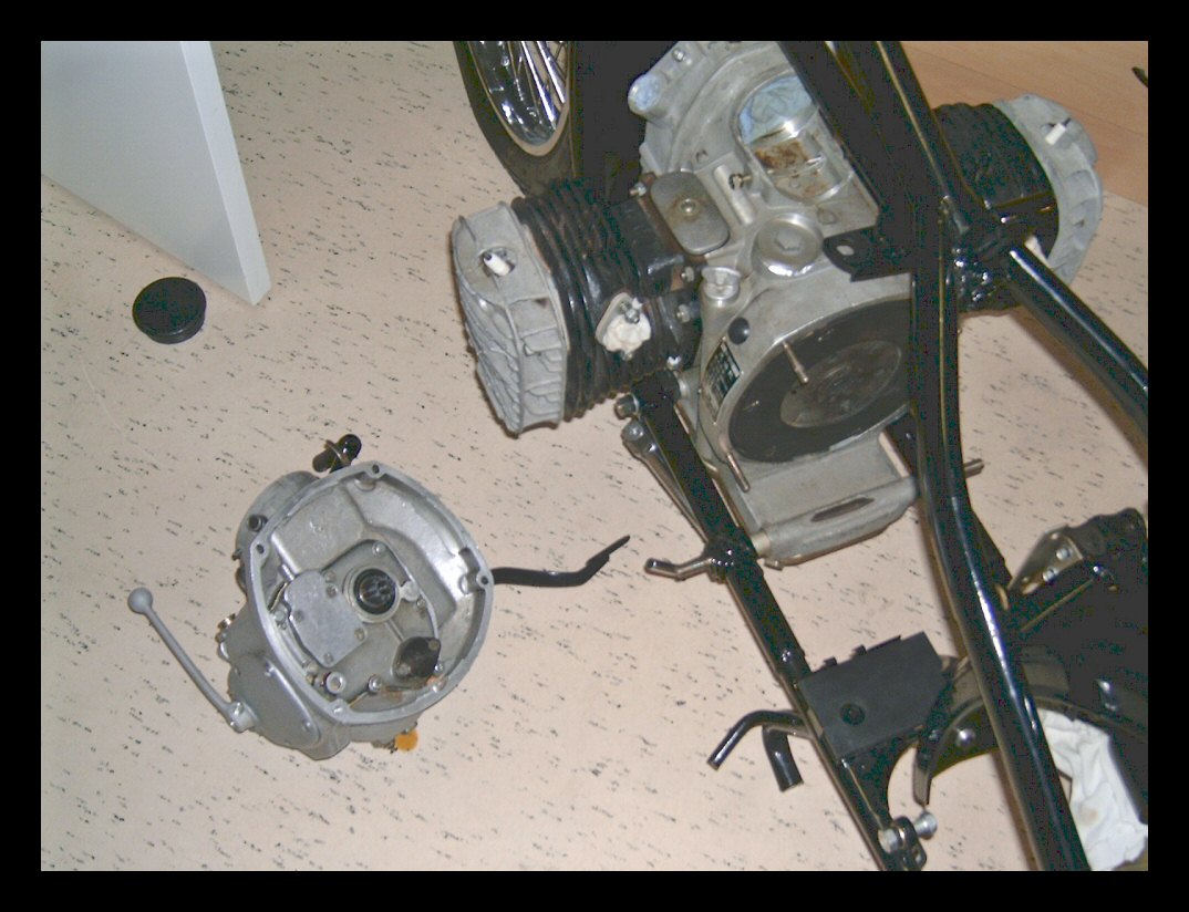
The solo gearbox looking smart..... | ||||
 |
Aligning the rear-drive axle and the rubber coupling is easy. Shift the rubber coupling on the rear drive axle. Turn the rear drive housing counter-clockwise, move the front end of the axle with the coupling so that the rubber aligns with the outgoing axle of the tranny. Turn the drive housing clockwise with force and slide the coupling in its place. | ||||
| Before you do all this, do not forget to grease the rear cardan jont. It needs grease once in awhile to operate for years without any trouble! | |||||
 |
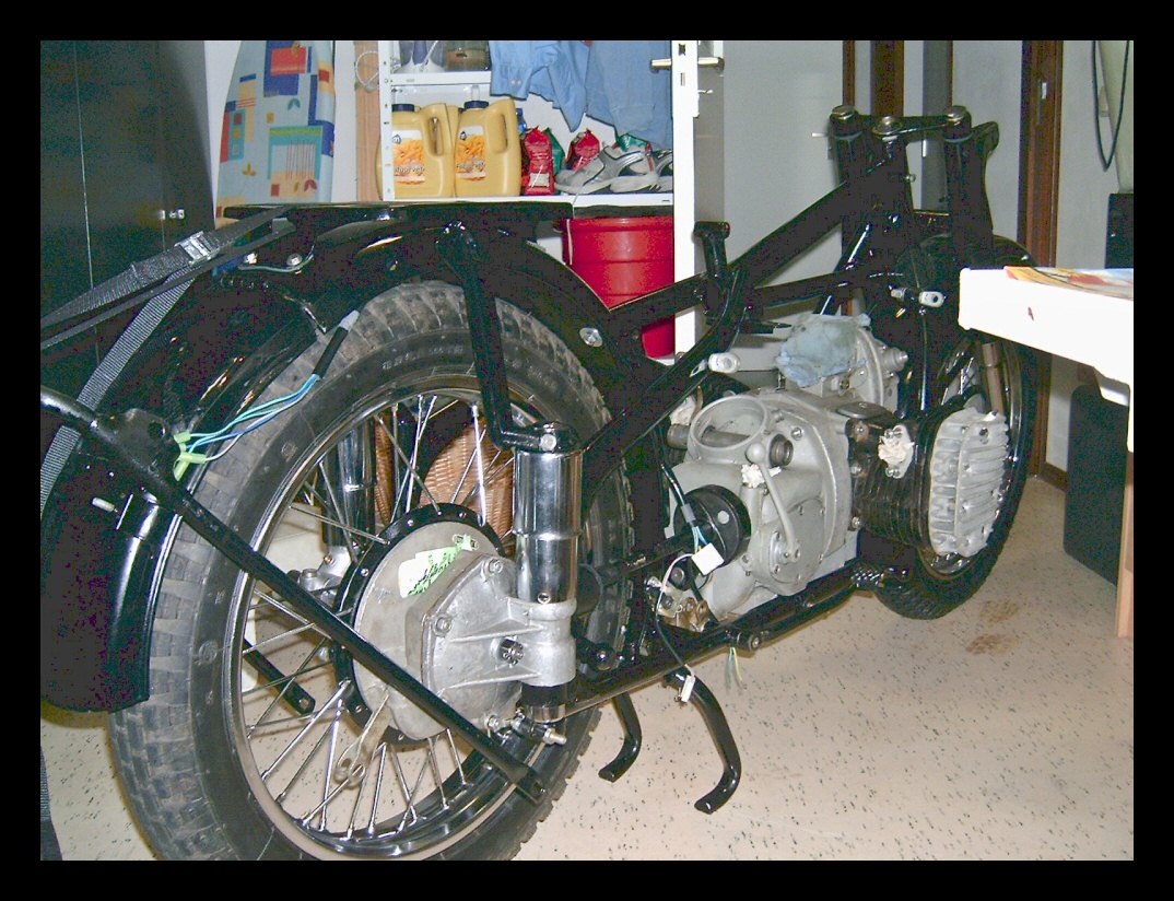
Finally, the M1M is standing on its two wheels again! | ||||
| Part VI | |||||
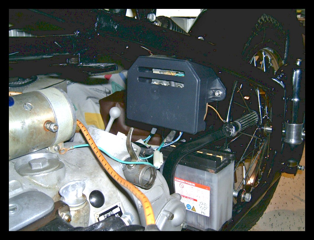 |
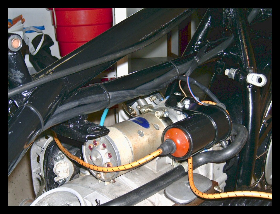
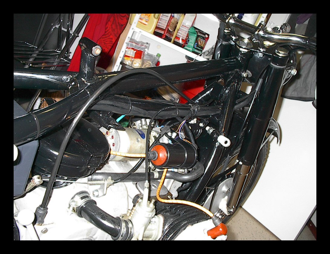
Also fed up with the rather "creative" way our factory workers have thrown in the wiring harness? You also don't like the cable mess clearly visible below the driver's seat? The solution is simple: rotate the box holding rectifier, starter solenoid and regulator half a circle and there you go! | ||||
 |
All you need to do is to relocate the two holes with M6 nuts in the metal backplate. Now the cabling harness sits at the bottom, just above the battery. The thick red + cable can be made much shorter. The thick blue wire to the starter motor can be located much more out of view. | ||||
 |
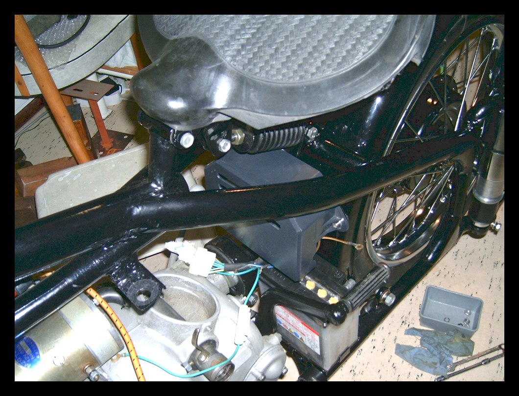
Plus the minor advantage of having the rectifier bridge much more in the driving wind, so it cools better. Check the vertical position of the new top end of the plastic cover with the saddle spring. These two better not touch each other. If in doubt, enlarge the M6 mounting slots in the mounting bracket and lower the electrics box a bit. | ||||
 |
All electric appliances are in place, waiting for the final cabling. Here endeth this lesson. | ||||
| Part VII | |||||
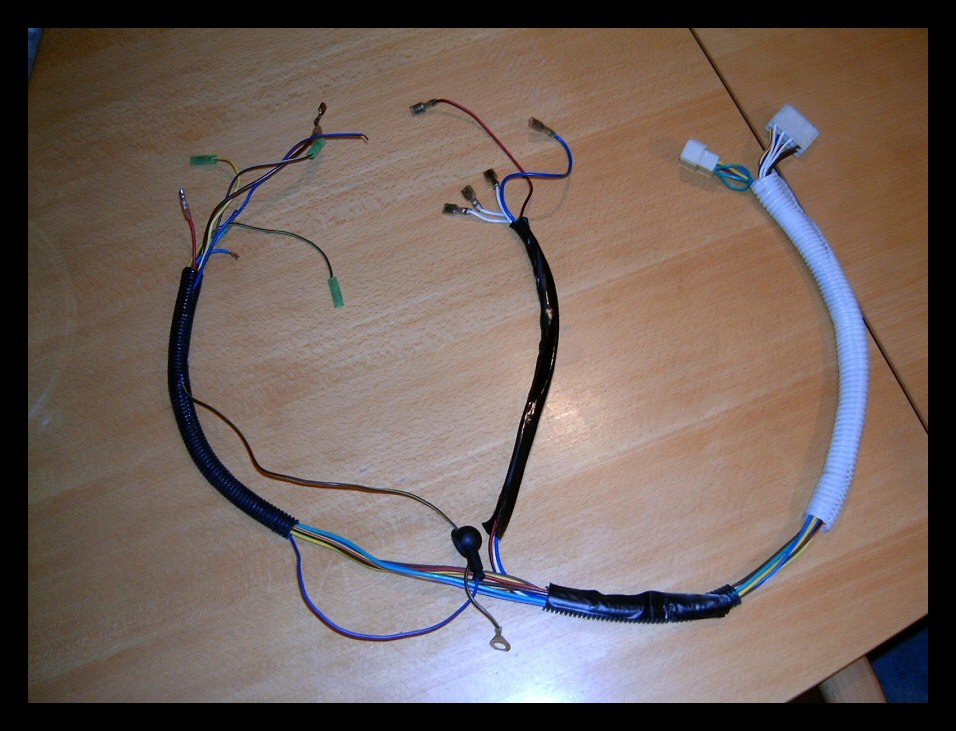 |
This is the original main cable harness. Hmmm, they used flexible pipes which are normally used in house construction, not the common soft PVC tubes. Time to change that into a real harness. However, the quality of the connecting male/female plugs is quite good. | ||||
| But, do inspect them, one may still find a so-so connection and that is a guaranteed source of problems when corrosion in time does its job. | |||||
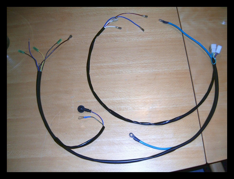 |
The same cabling harness done properly. | ||||
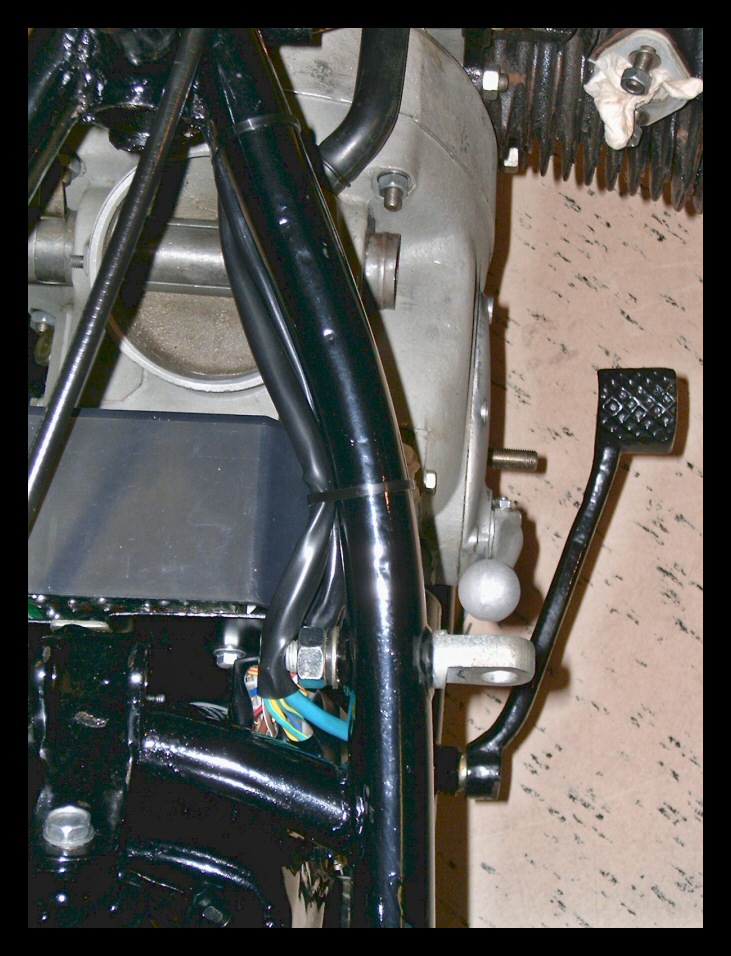 |
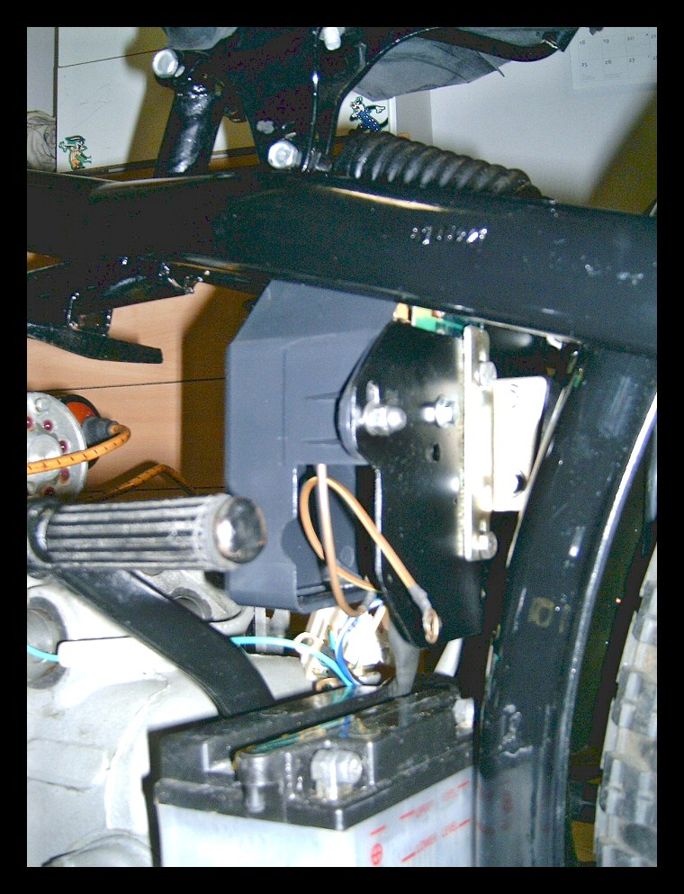
Now its time to install the harness and guide it along the frame tubes in such a way that it's tucked away as good as possible. We see the two connectors hidden behind the carrying plate of all the electric stuff like the rectifier unit. | ||||
 |
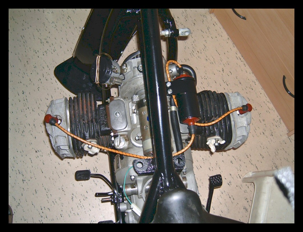
The blue/green thick power cable to the starter motor comes out the main tube at the right spot and is bolted onto the main lead. The rest of the cable harness goes all the way into the headlight body. The diversion cable for headlight ground and the +12V for the ignition coil are clearly visible. | ||||
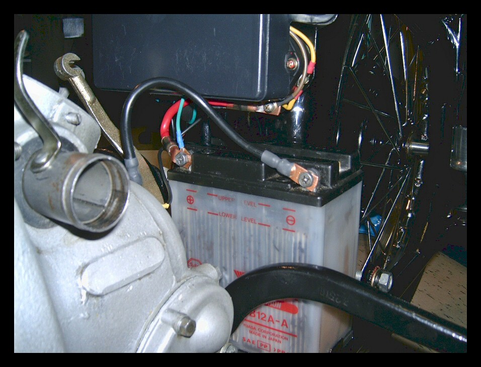 |
The space between battery (never mind this specimen, this is just a dead placeholder) and electric parts box shows the two thick and thin 12V + and ground leads. The result is a much neater overall look and improved reliability as far as the electrical wiring system goes. | ||||
| When building up the wiring, it's a good idea to work in modules. Check the ignition system first, apply 12V to the correct terminal and see if the two plugs show sparks when the engine is kicked. Then check the starter motor circuit. Apply power again, apply +12V to the correct wire and check if the solenoid clicks, check if the starter motor cable gets +12V when the solenoid clicks. Now check the cabling to the AC power generator and check if all cables are connected to the terminals inside the electric parts box. Use your Ohm-meter for this. Then check the taillights and brake lights, or if not mounted like we see here, check if the correct cable gets +12V when power is applied to the correct wire in the headlight. Do this before you fix all cabling with nylon straps. When all functions are go, strap the cable harness to the frame tubes. | |||||
| Part VIII | |||||
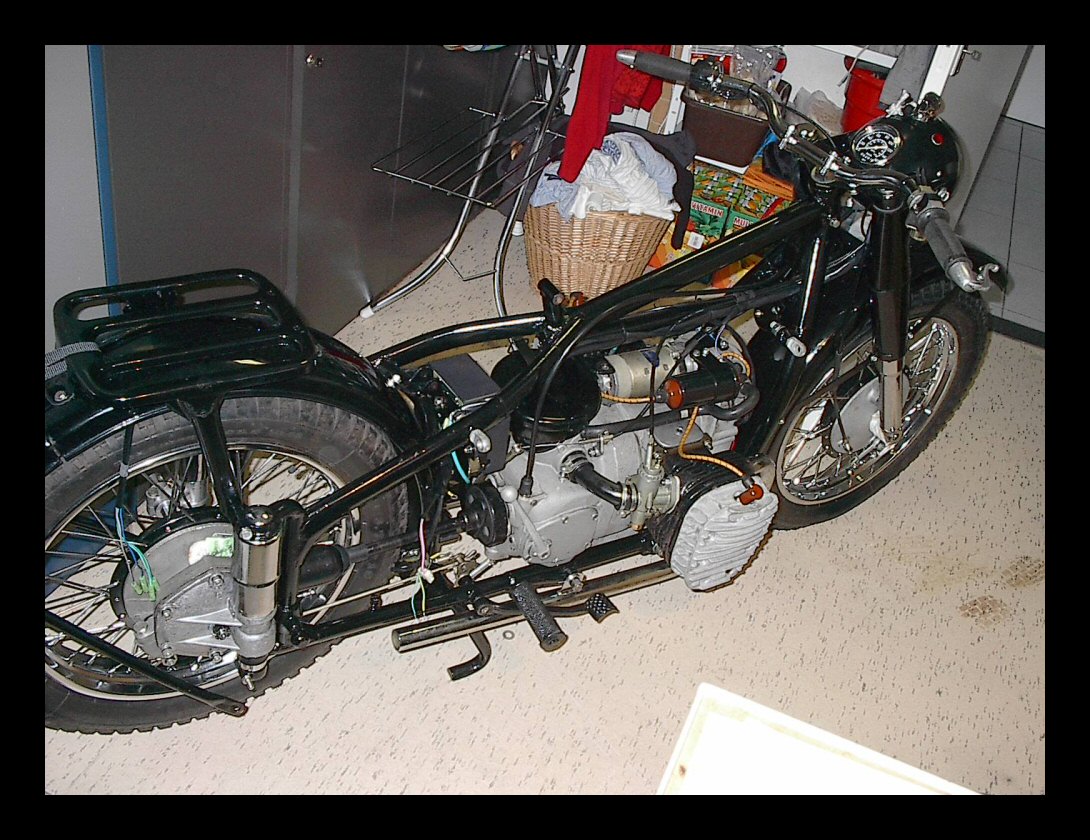 |
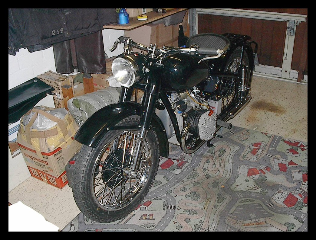
Almost finished! Cabling and Bowden cables are in place. The headlight is mounted as are the steering bar and controls. The exhaust tubes are where they should be. Now for some final cabling at the taillight and the brake switch and some other minor issues like the driver seat, gas tank and the mufflers. | ||||
 |
Tomorrow I will fill the engine and gear cases with (respectively) SAE30 and SAE80/90 EP and let the engine make its first revs again. | ||||
 |
We have a very bad weather forecast for the
Easter weekend with lots of snowstorms (!) so I do not
think that I will be be making much test drives... And now for the final steps! |
||||
| Part IX | |||||
 |
Finally finito! Yesterday evening my M1M rebuild project came to its conclusion, bar some very minor details like a mirror and the reflector at the bottom of the rear fender. But, for the rest, everything is A-okay ! | ||||
| I found the bug in the AC-generator/charging
circuit for which I posted a question on the Yahoo CJ
users group. It turned out, that the diode board was fine
all the time—one may not (!) measure the diodes
correctness while the board is still connected to the
AC-generator. I can always learn I guess... I took the
board completely out and checked the diodes again. All
are okay now. So, what could then be the problem? Back to
Mr. Frazer's diagnosis guide. If the rectifier board is
okay and the stator and rotor windings as well, then it
MUST be the voltage regulator. And indeed it was. The good thing about diving into these topics quite deeply is that one understands what the various components do and how they do it. The basic function of the voltage regulator (VR) is in its name and it does it by controlling the applied voltage to the AC-generator's field winding, i.e. the rotor. When the system is switched on, the AC-generator is "excited" by applying the full battery voltage to the field winding via the charging lamp. This leads to 0.88V tension at the field terminal from the generator. The VR does this by having a solenoid switch which is closed at rest, so when no power is generated by the AC-generator, this switch simply connects the FIELD and EXCITER terminals from the VR. Therefore, its internal resistance must be 0 Ohms when in rest. Mine was not! It showed ca. 155 Ohms between the two terminals in its rest position! Sidestep: This resistance of 155 Ohms is used as the first step of regulating the field voltage. When the AC-generator starts spinning because the engines starts, the EXCITER voltage quickly jumps to ca. 14V and this causes the solenoid to start working and thus it opens the contact, now two resistors with in total 155 Ohms feed a much lower voltage to the FIELD terminal. And the charging light goes off, by the way. This process obviously results in dropping the magnetic field inside the rotor and the regulating cycle starts to work. Actually, a next circuit built into the VR takes care of the even higher voltages which appear when the engine increases its RPM, but that does not concern us here. Back to my VR. If it does not show 0 Ohms when in rest, then the contact is dirty or blocked or something. So, I opened up the plastic case and—o and behold—a tiny dust particle was sitting between the contact points. No contact could be made and this caused my VR to show the 155 Ohms of the activated position, but now in its rest position. The result of that is, that the field exciting voltage is now way too low and the AC-generator can not start working. The solution was simple: Clean the contacts and there you go! I checked the operation without mounting all parts in their place and now the generator and charging were fine again. Nice 14.5V at ca. 3000 RPM. Finally I could install all components in place and finish the bike by making a sturdy battery bracket. |
|||||
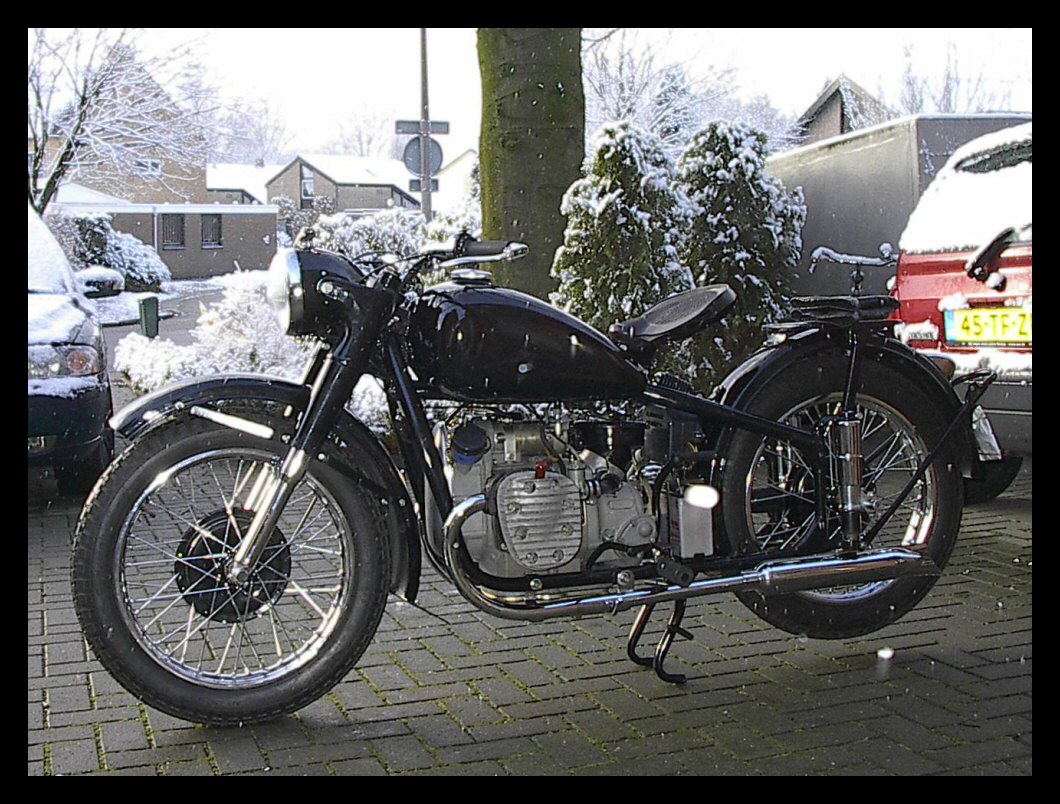 |
This picture today, March 25th, at 8 am. Nice weather for taking my bike to the appointment at my road licensing authority. At 9.30 am the license officer checked the bike against regulations and at 11.30 am I had a new license for this Chang Jiang 750 M1M. | ||||
| One thing is sure, spring will come and I will be enjoying it on this solo CJ750! | |||||
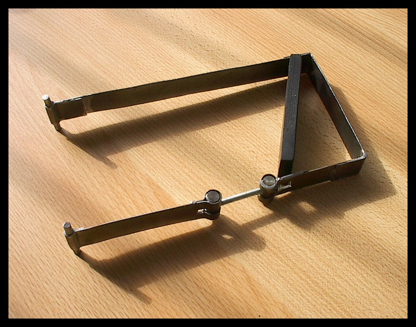 |
Final picture: The battery bracket (yes, it still needs some paint...). | ||||
| Part X | |||||
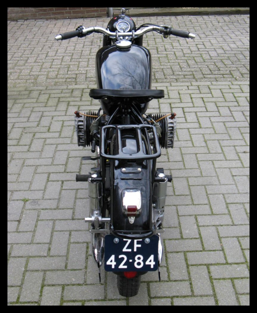 |
Just to wrap things up, here are the final-final pictures of the CJ750 M1M with official license plate, insured and ready to go. I tested the bike this evening for some 60km with full lights on and apart from a sticky brake switch, all is OK. | ||||
| The bike behaves really good as a solo motorcycle, at low or higher speeds one can take off one's hands from the steering bar and it keeps on driving in a perfect straight line. Curves are taken well and there is not any sign of steering wobble at any speed. | |||||
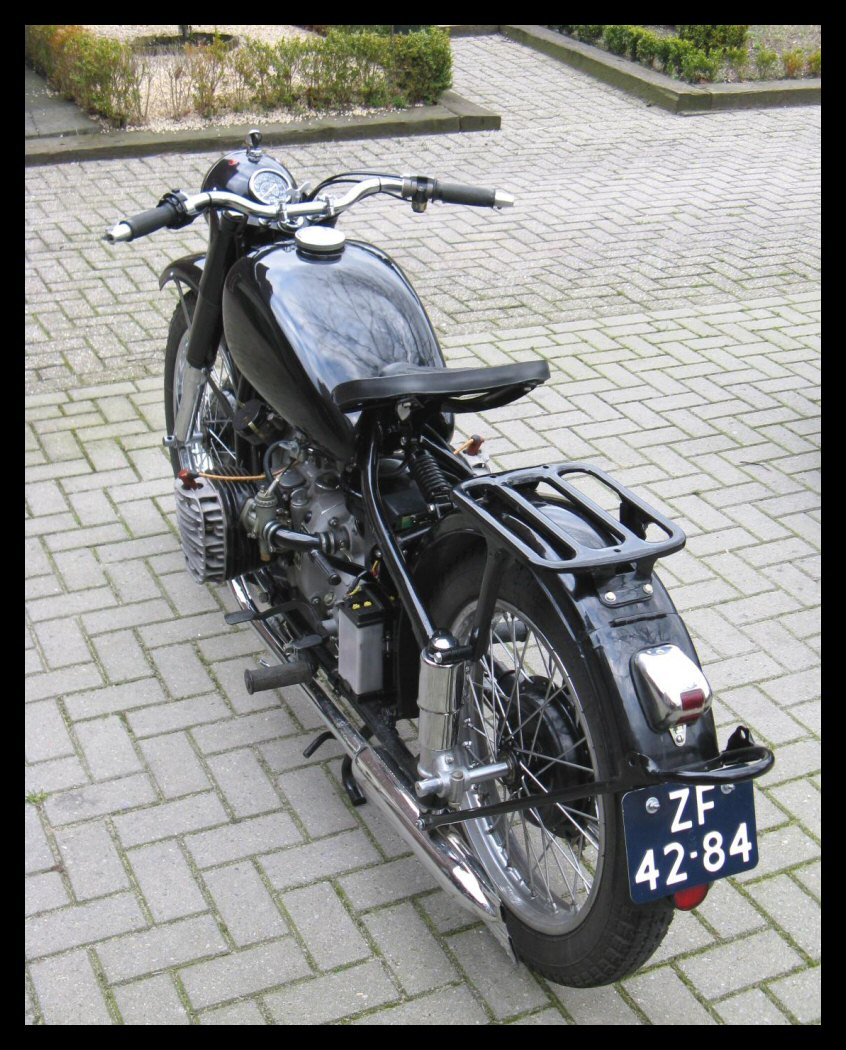 |
With the carbs still having the break-in pins at the lowest position, max. speed is 80 km/h on a flat road. The engine sounds well, the gearbox shifts into all gears without any problem and the clutch releases well. | ||||
| So, let's see how the braking in period is mastered in the coming springtime weeks! | |||||